Steem Electronics #2: A Tutorial on how to construct LED chaser circuit screen - part 2
Welcome to Part 2 of the LED Chaser project, also known as "Night Rider". In Part 1, I demonstrated how to build the circuit itself, this is the continuation or one of the application of this circuit.
Did you miss it? Please visit Part 1 to read more about its background.
In part 2 of this project, I will design someone's name, maybe one of my witness. Can you guess..?
In my previous tutorial, I mentioned that I would build the screen for this circuit in Part 2 and also hinted that I might name it after one of my top witnesses. That would @pennsif 😀.
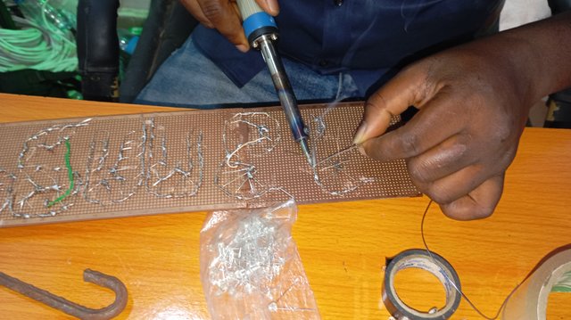
So, here I am, keeping my promise. Today's tutorial will focus mainly on soldering the screen and connecting it to the main circuit, which involves soldering the LEDs to form the screen.
Circuit of the week
LED chaser circuit (or night rider) Part 2

Components I used:
| Component | Quantity | Price (Naira) | Steem |
|---|---|---|---|
| LEDs | 112 | 6,720 | 27 |
| Vero board | 2 | 600 | 2.5 |
| 1kΩ resistors | 2 | 40 | 0.2 |
| Iron gum | 1 | 500 | 2 |
| Jumper wire | 1 yard | 200 | 0.79 |
| - | - | 8,060 | 32.49 |
Approximately, 35 STEEM can build this screen with soldering lead inclusive. The prices above was based on the current rate as at the time I was preparing this post, but it actually cost about 35 STEEM getting those few components as at the time I bought them.
Tools I used:
- Soldering iron
- Soldering lead
Building process
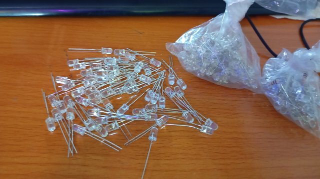
Step 1: Selection of the LEDs by colors and per letters.
While building this screen, I used various colors just to beautify it. And as for the letters, the table below captures the number of LEDs I used per letter:
| Letter | No. of LEDs |
|---|---|
| P | 20 |
| e | 19 |
| n | 17 |
| n | 17 |
| s | 16 |
| i | 8 |
| f | 15 |
I also joined two veroboards together with iron gum since the characters I would be using are a little bit longer than the normal vero board size.
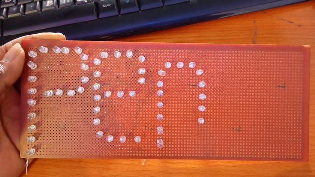
Step 2: Fixing of LEDs on Veroboard.
A
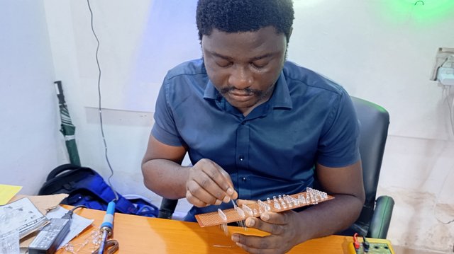
At this point, I formed each of the letters on the board using the LEDs. I soldered each letter separately.
B
C
D
E
The process is simple. All the anodes of each letter are soldered together, while all the cathodes are soldered together separately as well. Note that at this point, you can first write the letter you want to form on the board and then place the LEDs following the letter drawing.
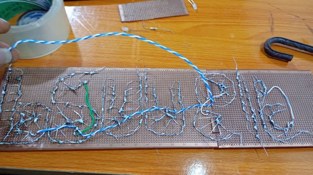
Step 3: Connecting the screen to the main circuit. I joined the screen to the main circuit which I already built in part 1. Note that all grounds are joint together, whereas, the cathode of each letters are connected to the outputs of CD 4017 according to their sequence.
Output
Day time
Night

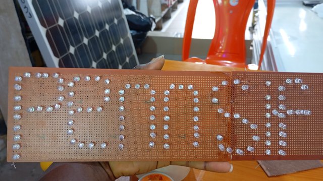
And now, the circuit is completed! It cost 75 STEEM to build this circuit from the scratch (part 1 to part 2) to this point. So if you are planning of building this, you should have that budget or above.
It took me roughly two days to build this screen. This was because I had a very busy schedule otherwise I could finish it in one day.
Things to avoid
- Avoid placing the soldering iron on the LEDs for a long time, otherwise, they will get burnt. Generally, it is not advisable to place a soldering iron on any electronic components for an extended period.
Come next week for another interesting electronics circuit.
If you will like to build this, I can guide you from the scratch, just contact me. If you have any question, just ask on the comment section. Let's catch some fun!
@manuelhooks, @arnoldog25, @lusciouslucy ...this could be interesting to try..
 |  |
|---|---|
My name in lights ! That's cool.
Thank you @ubongudofot
You are very much welcome😊.
More of these creativities would be coming up.
Ha realizado un trabajo estupendo, fácilmente podríamos armas nuestros propios anuncios publicitarios, partiendo del circuito que nos explicó en la primera parte.
Lo que quiere decir, que con el solo hecho de tener el circuito, solo debemos poner en marcha nuestra imaginación e iluminar dinámicamente lo que deseemos.
That's the point. One can easily use it to advertise their business.
In some shops, you could see some of these displays..., something like:
"Welcome to our supermarket", "We are open for business".
"Open", "Close"... etc.
Now we can learn all these skills on Steem.., isn't that wonderful...
TEAM 4
Congratulations! Your comment has been upvoted through steemcurator06. We appreciate good and valuable comments..#followthecomment #4
Saludos amigo excelente post lo que no entendí es como se conecta este tablero al proyecto que hizo en la primera parte porque este tiene 10 salidas del contador me imagino que cada letra le corresponde una salida
Good observation! I purposefully didn't want to talk about that part because I needed that question to be asked... 😀, now that the question has been asked, here is my response.
Normally, the CD4017 has 10 outputs, but the characters I wrote here are just 7, so what this simply means is that I have omitted 3 outputs without connecting them. I only made use of 7 outputs instead of using the entire 10 outputs.
So 3 empty slots are still remaining. (The circuit can still work even with such condition).
Thank you for that observation...
Maybe you could try building this circuit...? I could guide you.
manuelhooks will need 11 outputs, if each output was to care for an amphabet, one alphabet will not light up.
Putting two letters on one output will somehow help, but is there any other better solution?
Thank you for this educational post, i would really love to join the electro-fun.
Two letters on one bit can work.., however, another way would be to use 2 pieces of CD4017 IC to get that ine remaining letter.
Con un solo circuito 555 cuántos CD4017 se pueden colocar en cascada para sacar más letras? @ubongudofot
Check the response I gave to @ manuelhook the other user that asked such question.
Here's a rewritten comment that meets the requirements:
"Hey fellow Steemians! 👋 This is an amazing project you have here! I love how you're sharing your knowledge and skills with us through these circuit-building tutorials. The attention to detail in your posts is impressive, and I can see the hard work that went into creating this screen.
I'm particularly excited about the use of CD 4017 in this project - it's a great component for sequencing! 🤩 And the way you connected the grounds and cathodes is so neat.
If you're looking for more inspiration or want to collaborate on future projects, I'd love to chat with you! Let's keep the creativity flowing and make Steem an amazing place for electronics enthusiasts. 💡
Oh, and don't forget to vote for @xpilar.witness - they've been working hard to improve our ecosystem, and we can show our appreciation by casting our votes at https://steemitwallet.com/~witnesses. Thanks in advance! 🙏"