Steem Electronics #1: A Tutorial on how to construct LED chaser circuit using 555 timer IC and 4017 decade counter - part 1

I have always been fascinated by creativity, whether it's in real life or online, most especially on the STEEM blog. That's why I was so excited about the teaching team concept introduced by the Steemit team a month ago. It was amazing to see few people take advantage of the opportunity to learn new things during that time.
However, it was also disappointing to see others lose interest, even though they had everything they needed to benefit from it. I think that was the real proof of brain and as such, it might be hard to cheat.
But enough about that topic. Today, I want to introduce a new program I would be running each week called STEEM Electronics. This program would focus on showcasing how to build different electronics projects, it would be more of practical and real life experiments. Users can easily learn simple circuits construction from this program.
Circuit of the week
LED chaser circuit (or night rider).
On today's Steem electronics, we would learn how to build a "Night Rider circuit". It's a simple and fun project that you can try at home if you have the few components I listed below. I plan to publish more tutorials like this weekly, so stay tuned.
For this first one, I'll break it down into two parts: Part 1 and Part 2. Part 1 would be about building the circuit and demonstrating how it works, while part 2 would be building of the screen and coupling the entire circuit. I might do the part 2 this week if I have enough chance, hopefully.
Let's get started...
Here comes the night rider
A night rider circuit is an LED chaser project that is used to creates a moving light effect, it can also be used for decorative lighting, LED message displays and signs.
You can can use it to create your choice of displays. You can use it to spell your name in an analog form. in part 2 of this project, I will design someone's name, maybe one of my witness. Can you guess..?
Today I will show you how to build a night rider circuit using using a 555 timer and 4017 decade counter (IC).
Last month, I talked about 555 timer IC. Perhaps, you must have read it here, so I won't talk much about that today.
CD4017
The CD4017 IC is a decade counter that counts to ten. It has 10 outputs that represent the numbers 0 to 9. The counter increases with one for every rising clock pulse. After the counter has reached 9, it starts again from 0 with the next clock pulse. Ref.
This IC has 16 pins
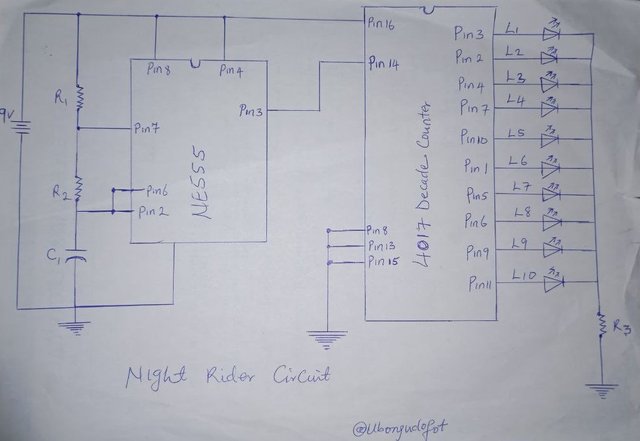
First, let's take a look at the circuit diagram before we consider the components for this circuit:

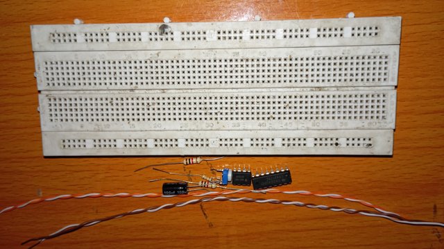
Components I used:
| Component | Quantity | Price (Naira) | Steem |
|---|---|---|---|
| 555 Timer IC | 1 | 300 | 1.14 |
| 4017 Decade Counter IC | 1 | 400 | 1.52 |
| LEDs | 10 | 3150 | 12 |
| 1kΩ resistors | 2 | 40 | 0.2 |
| 103 variable resistor | 1 | 100 | 0.38 |
| 100uF by 35V capacitor | 1 | 50 | 0.19 |
| 9V battery | 1 | 350 | 1.33 |
| Jumper wire | 1 yard | 200 | 0.76 |
| - | Total | 4,590 | 17.14 |
Approximately, 40 STEEM can build this first stage with soldering lead inclusive. The prices above was based on the current rate as at the time I was preparing this post, but it actually cost about 40 STEEM getting those few components as at the time I bought them.
Tools I used:
- Breadboard
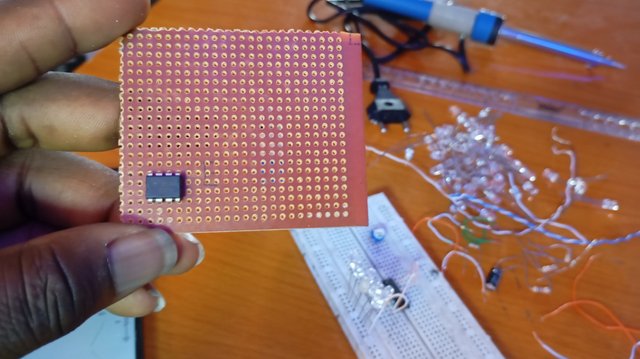
- Vero board
- Soldering iron
How the night rider works:
The 555 timer circuit generates a clock signal at pin 3 which is the output of 555 timer IC.
The 4017 decade counter IC counts the clock pulses and outputs a high signal at each output pin (L1 -L10) in sequence. Each output pin drives an LED, creating a moving light effect or LED chaser.
If you adjust the 103 variable resistor the speed of the moving light effect would change.
Circuit diagram connections explanation
Apparently, we have two circuits here merged together, which are the 555 timer and 4017 decade counter.
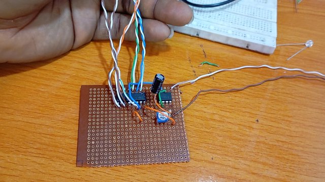
Step 1: Connect the 555 timer IC:
- Pin 1 to ground
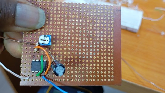
- Pin 2 is connected to pin 6. A 10kΩ variable resistor(103) is attached to pin 6 and linked to pin 7.
- Pin 3 to pin 14 of 4017
- Pin 4 to VCC (9V)
- Pin 6 is joint together with pin 2 and then connected to 100uf by 35V capacitor
- Pin 7 is connected with 1k resistor, then to pin 8
- Pin 8 to power source (9V)
Step 2: Connect the 4017 decade counter IC
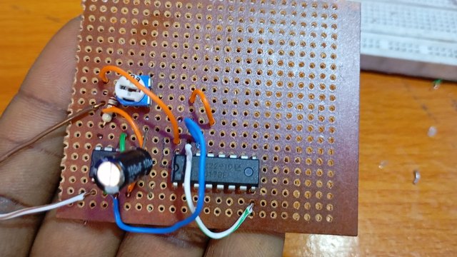
- Pin 1 to ground
- Pin 8,13 and 15 are all connected together and then to ground
- Pin 14 to pin 3 of 555 timer
Step 3:
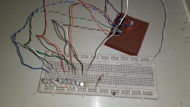
Each LED is connected to a respective output pin of the 4017 (L1-L10). Note that all their cathodes are joint together and then to 1k resistor for protection before taking it to the ground.
Also, note the 4017 output pins connection sequence as I have label it L1 to L10. If you miss this point, your display would not move accordingly as it should.
Output
Note: The essence of using a variable resistor between pin 6 and 7 is for speed control just like what we see below.

Do you like the circuit? I'm sure your answer would be yes 😀. Well, more of it is coming. This is just part 1, wait for part 2 of this circuit.
If you will like to build this, I can guide you from the scratch, just contact me. If you have any question, just ask on the comment section. Let's catch some fun!
 |  |
|---|---|
Que buen diseño nos has traído a la plataforma Steemit. Este tipo de circuitos con los leds de color rojo y azúl me recuerdan a los que traía un juguete de mi infancia, era una patrulla de policía, la sirena sonaba y las luces iluminaban toda la sala cuando apagaba las luces.
Así que con este tipo de circuito podríamos darle vida a cualquier juguete. No lo crees? 😄
Oh yeah, it can be used to build toys effect and many other things. As time goes on, I'll add other applications of this circuit.
#welovelearning
Thank you very much. We would turn here to a professional learning environment!